The BioCAT undulator beamline 18ID at the Advanced Photon Source, although now over 20 years old, remains a state-of-the-art instrument for biological small and wide angle fiber diffraction and macromolecular solution scattering (Fischetti, et al., 2004 J. Synchrotron Rad. (2004). 11, 399-405). It is capable of delivering well over 1013 photons/s into focal spots as small as 15 x 25 µm2 with the conventional beamline optics. The BioCAT beamline was designed by Dr. Rosenbaum (Argonne National Laboratory) and shares the same overall mechanical design of the SBC undulator 19-ID (Rosenbaum et al. J Synchrotron. 2006 Jan;13(Pt 1):30-45). Undulator “A” provides very intense monochromatic radiation in the 5 - 16 keV range with low angular divergence and a small source size. While it is possible to change the beam energy, in practice all experiments are done at 12 keV. A differential pump separates the vacuum structure from the storage ring eliminating the need for any windows between the beamline and the storage ring.
| Source | APS Undulator A |
| Monochromators | Si <111> |
| Energy Range (Si <111>) | 5-15 keV |
| Energy Resolution (dE/E) | 2 x 10⁻⁴ (Si <111>) |
| Minimum Spot Size (µm2 FWHM) | < 1000 x 1000 (unfocused), ~15 x 25 (focused at detector 3.5 m from sample) |
| Monochromatic flux (12 keV) | 5x10¹³ ph/s |
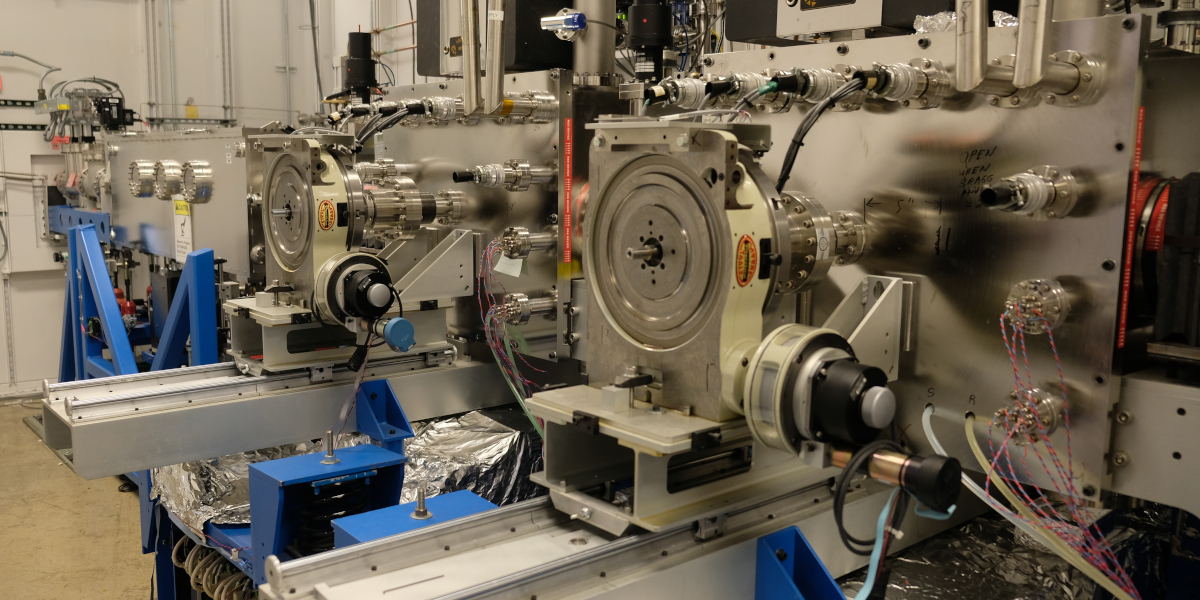
The first optical element is a set of white beam slits located just downstream of the differential pump that can be used to define the incoming beam size as well as mitigate heat loading. There are two independent double-crystal monochromator assemblies. The upstream monochromator #1 has fixed Si(111) crystals to facilitate energy changes for the microfocus setup while the downstream monochromator #2 has a sagittal focusing second crystal assemblies that can provide horizontal focusing of the beam for the main SAXS camera. We have observed a FWHM of 15 µm in intensity profiles of the sagittally focused 12.0 keV X-ray beam at the focal point for a 2 meter SAXS camera (about 64 m from the source). The beamline mirror is used for harmonic rejection and vertical focusing but it easily can be withdrawn from the beam path when desired. In between the monochromators and the mirror is a diamond beam position monitor (Dectris Rigi) and a set of scatterless monochromatic slits that can be used as beam defining slits.
The current vertical focusing mirror is a dynamically bent flat mirror. Typical vertical beam profiles when focused for 1.5-3.5 m SAXS camera configurations are less than 25 µm FWHM. A monochromatic photon shutter allows the monochromator optics to stay warm while allowing the user to enter the experimental enclosure.
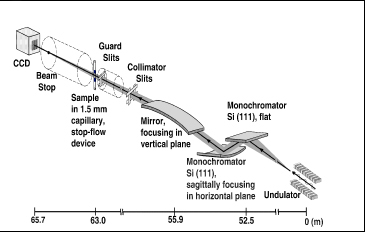
The experimental enclosure is 14 m long x 5 m wide x 3.3 m tall. The first 2 m are taken up by the scatterless vertical collimation slits and the downstream support, which incorporates filter/shutter assemblies, and a in-vacuum diamond intensity monitor and beam position monitor (Sydor DBPM) for the primary beam (I0) monitor. Before the vertical collimation slits is a beryllium window. All components upstream of this window are under high vacuum (10-7 – 10-8 torr); thereafter, all components are in rough vacuum (10-3 – 10-4 torr). The downstream support moves all these components under computer control to follow the beam as reflected off of the mirror. Downstream of this table is 6.4 x 1.5 m vibration-isolation table that is used for most small-angle diffraction and scattering experiments. Two more sets of scatterless slits are mounted on this table, the upstream one is used as anti-scatter slits and the downstream (just upstream of the sample) as guard slits.
The beamline control software is based on the Experimental Physics and Industrial Control System (EPICS) which is a distributed system using VME-based electronics with crate controllers running the proprietary real-time UNIX-like operating system VxWorks (Wind River Systems). Some equipment is run using The portable beamline control software package MX (Lavender, 2000). User interface software communicates over Ethernet via the EPICS Channel Access (CA) protocol or via MX servers. Beamline controls for EPICS are implemented using Tcl/Tk and Java menus as using the EPICS graphical control displays (MEDM). Other controls for MX and EPICS are written in python. These controls are all portable between different operating systems. Almost all user-facing controls are python GUIs.
The beamline stepper motors and data acquisition systems are controlled by two VME crates with Motorola MVME controllers. Many beamline motors were chosen to be DC servos because of their advantages in high torque, speed, and power consumption over stepper motors. Three 16-channel Delta Tau PowerPMAC servo motor controllers control the beamline optics and XY positioning stages. Stepper motors are controlled by five 8-channel Oregon Microsystems OMS-58 stepper motor controllers with Step-Pak drivers.
For time resolved data acquisition there is a Struck 3820 multichannel histogramming scaler with 32 inputs. For conventional scans there is also a Joerger VCS16 scaler with 16 inputs. There are four fast 100 MHz voltage to frequency (V to F) converters (V2F100, Quantum Detectors) and one slower 1 MHz V to F (Hytec VFC 2504, Hytec Electronics Ltd). Most fast experiments are controlled by two SRS DG645 pulse/delay generators (Stanford Research Systems), which together provide up to 8 controllable pulse outputs for controlling shutters, detectors, and other equipment.
External equipment (area detectors, shutters) can be interfaced to the control system using a digital I/O board (two LabJack T4s) with 16 input and 16 output channels. There are 8 current amplifiers (Keithley, model 42) which are interfaced through the RS232 ports on the beamline workstations. We have designed soft EPICS IOCs for these devices so that they can be accessed from other computers in exactly the same way as the VME modules.
Two XIA model PF2S2 filter assemblies contain a series of aluminum filters that allow at least 3 decades of beam attenuation (at 12 keV). A standard uniblitz x-ray shutter (XRS6) capable of 5 ms exposures is routinely used for most experiments. We also have a shutter capable of <500 µs minimum exposure time consisting of two electrically-activated, inclined blade-type shutters in series (Model LS500, NM laser products Inc) with ca. 1 ms latency available upon request.